Tested and certified as a Type 2+3 protector according to the UNE-EN IEC 61643-11 standard and the REBT GUIDE-BT-23.
Suitable for equipment of Categories I, II, III, IV according to ITC-BT-23.
Dual terminal connection for easy wiring (limited to 63 A).
Compact multipolar protection.
Protection in common and differential mode.
Coordinated with the protectors of the ATSHOCK, ATSHIELD and ATSUB series.
Short response
time.
They do not produce deflagration.
They do not at any time cause the interruption of the supply
lines.
Great energy bypass capacity.
Limits consecutive mains currents.
Potential-free output for remote warning.
The protectors of the ATCOVER series have been tested in official and independent laboratories to obtain their characteristics according to the applicable standards.
| Reference | AT-8112 |
| Rated voltage | ORn | 230 VAC |
| Maximum operating voltage | ORc | 275 VAC |
| Nominal frequency | f | 50 – 60 Hz |
| Nominal discharge current per pole 8/20μs | In | 10 kA |
| Maximum current per pole (wave 8/20μs) | Imax | 30 kA |
| Protection level for wave 8/20μs at In | ORp | 900 V |
| Protection level for wave 1.2/50μs | 700 V | |
| Residual voltage with combined wave 6 kV/3 kA | 700 V | |
| Response time | tr | 25 ns |
| Previous fuses | 125 A gL/gG | |
| Maximum short circuit current | 25 kA |
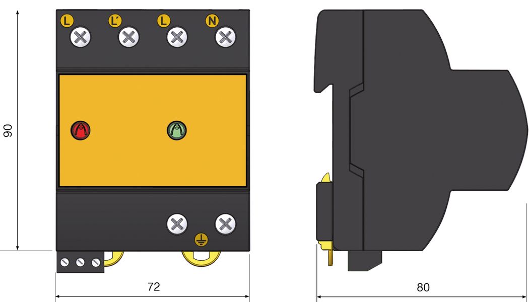
| Long | 72 mm |
| High | 96 mm |
| Wide | 80 mm |
| Weight | 340 gr |
| Number of DIN modules (DIN 43880) | 4 |
| Working temperature | -40 °C to +70 °C |
| Status of the protector | Interior |
| Housing protection | IP20 |
| Protection categories according to REBT | I, II, III, IV |
| Types of tests according to UNE-EN 61643-11 | Type 2+3 |
| Fixation | DIN Rail |
| Housing material | Polyamide |
| Insulation resistance |
> 1014 Ω |
| Self-extinguishing housing | Type V-0 according to UNE-EN IEC 60707 (UL94) |
| Connection type | Parallel (one port) |
| Number of Poles | 2 |
| Protector failure message | Double warning of non-protection by means of a fault indicator light and a green pilot of good operation. |
| Minimum multi-row section | 4 mm2 |
| Maximum multi-row section | 35 mm2 |
| Minimum unifilar section | 1 mm2 |
| Maximum unifilar section | 35 mm2 |
| Screw thread | Philips H2 |
| Tightening torque | 3 N·m |
| Connection |
Maximum unifilar / multifilar section: 1.5 mm2 |
| Contact output | Switched |
| Operating voltage | 250 VAC |
| Maximum Current | 2 A |
Ensayos certificados según norma UNE-EN IEC 61643-11.
Cumple con los requisitos de UL 1449.
Normas de aplicación: UNE 21186, UNE-EN IEC 62305.
Conformidad con las directrices CE.


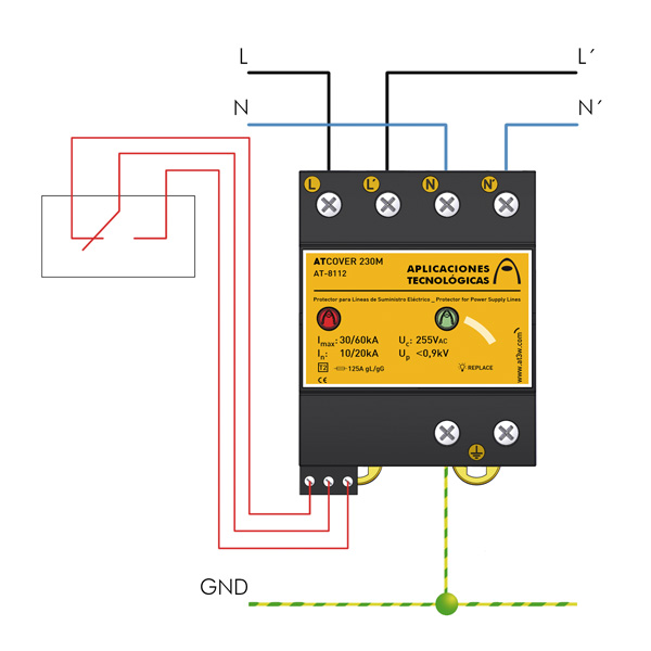
ATCOVER protectors are installed in parallel with the low voltage line.
When they are installed in combination with other protectors it is necessary that they are separated by a cable of at least 10 meters or, if this is not possible, by an ATLINK type inductance, in order to achieve the correct coordination between them.
The installation must be carried out without tension on the line and can only be carried out by authorized professionals.
Grounding is a must. For the protection to be correct, the grounding of the entire installation must be joined, directly or by means of sparks, and their resistance must be less than 10 Ω.
If in its use or installation the indications of this sheet are not respected, the protection ensured by this equipment may be compromised.
WhatsApp us